How to Test a Motherboard With a Multimeter
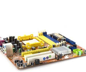
The motherboard of a computer provides the platform for the majority of the machine's components, allowing the use of complex circuitry without needing confusing wiring schematics. Testing or troubleshooting a PC motherboard can be done at home, as a simple multimeter can be used to test various circuits and determine general electronic problems.
Testing the DC Voltages
Step
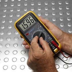
Make sure the 20-pin ATX connector is in and the computer is hooked up to AC power. Set the multimeter to 20V DC. Using the black multimeter probe, probe the backside of the connector and set the black probe in contact with pin 15, 16, or 17 (GND pins).
Step
Use the red probe to probe the following pins (looking for the readings indicated in the parentheses): Pin 9 (Purple, VSB) should be at 5 V (any other reading indicates a problem with the PSU); and Pin 14 (Green, PS On) should be between 3 and 5 volts. Press the PC power switch, and the PS_On value should drop to 0. Other readings indicate a faulty switch.
Step
Use the red probe to check Pin 8 (gray, Power_OK), which should be above 2.5 V; this signals that it is okay for the computer to start. Pressing reset should make the Power_OK reading drop to 0 and then climb back up.
Testing the PSU and Motherboard for Short/Open Circuits
Step
Unplug the computer from AC power and allow several minutes for any excess charge to drain. Set the multimeter to the lowest Ohm setting (around 200) and touch the leads of the probes together to zero the meter. Touch the two leads to the bare metal of the computer's chassis; the zero reading should be the same.
Step
Carefully remove the ATX connector from the motherboard. Keep the black probe on the metal of the chassis and use the red lead to check the PSU's A/C ground pin and the black wire pins on the D/C connector; these should all read zero.
Step
Keep the black lead on the chassis and use the red probe to check the values of the colored wire pins on the D/C connector. All colored wires should give a reading of 50 or greater.
Step
Remove the CPU from the motherboard socket. Use the ATX 20-pin chart to refer to pin numbers on the board's connector. Keep the black lead on the chassis and use the red lead to test the GND pins on the motherboard connector: Pins 3, 5, 7, 13, 15, 16, and 17 should return a reading of zero. Any other reading indicates a possible faulty connector.
How to Get Into MSI BIOS
The BIOS (basic-input-output-system) is where the hardware settings for your computer are stored. If you are having boot problems with your computer, the BIOS settings are the first thing you should check. However, entering the BIOS on a computer with an MSI motherboard requires that you follow certain steps in the correct order.
How to Enter MSI BIOS with No Password
Step
Press the "Delete" key several times, as the computer displays the POST screen to enter the BIOS area. The POST is the "Power On Self Test" that the computer performs to check the hard drive, memory and processor on your computer. If your computer displays an MSI logo screen instead of the POST screen, press the "Tab" key to display the POST screen, and then tap the "Delete" key a few times.
Step
Refer to your MSI motherboard manual for specific setting descriptions and instructions.
Step
Make changes to the settings in the BIOS as needed and click on the "Save Changes and Exit" button on the main BIOS screen.
How to Enter MSI BIOS that Has a Known Password
Step
Tap the "Delete key a few times while your computer displays the POST screen. If your PC displays a logo screen when powering up, go to the POST screen by pressing the "Tab" key. Then, press the "Delete" key.
Step
Enter the administrator password for the BIOS area and then press the "Enter" key. If you enter the correct password, you will then enter the main BIOS screen. If you enter an incorrect password, the system will prompt you to enter the correct one.
Step
Make needed changes to the BIOS settings and save. Your computer will then restart.
How to Enter MSI BIOS that Has an Unknown Password
Step
Power down the computer and unplug the power cord.
Step
Place the computer on a flat surface. Then, remove the screws on the rear of the computer, so that you can remove the chassis cover. Place the chassis cover aside.
Step
Refer to the owner's manual for your MSI motherboard and locate the "Jumper Configuration" diagram. Locate jumper "JBAT1" on the diagram. Find the jumper on your MSI motherboard.
Step
Remove the jumper from pins 1 and 2 and place it on pins 2 and 3. Wait for 15 to 20 seconds and then place the jumper back on pins 1 and 2. This will reset the BIOS to factory default settings and remove the password.
Step
Close up the computer and plug the power cord in.
Step
Enter the BIOS by pressing the "Delete" key during the POST.
How to Check for Bad SMD Capacitors
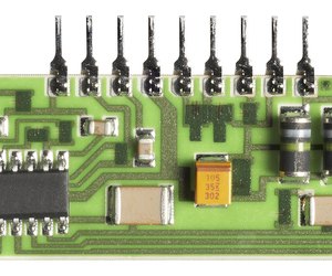
Capacitors are a common source of failures in electronic equipment. They can fail in different ways. Some fail due to over-voltage or voltage spikes. Electrolytic capacitors experience failures that begin as tiny current paths through the dielectric and progress to eventual shorts between the plates. There are three approaches to troubleshooting suspected capacitor problems -- visual inspection, in-circuit testing and out-of-circuit testing.
Step
Look for any capacitors showing signs of discoloration or charring. Sometimes a failure is obvious. Look for cold solder joints that may indicate the presence of heat at one time. Use a magnifier and look for any cracked capacitors, a sure sign of failure.
Step
Test capacitors in the circuit with a multimeter set to measure resistance. Be aware that other current paths may exist on the board, making the multimeter results unreliable. If a capacitor is connected between the gate of a MOSFET and ground, for instance, and the mulitmeter shows a short circuit, either the capacitor or the MOSFET could be bad.
Step
Remove the capacitor from the circuit to test it. Capacitors are readily removed with thermal tweezers or a hot-air de-soldering hand piece. Test the capacitor with a multimeter set to measure resistance. A good capacitor will test over the limit (OL) of the meter display. Multimeters usually have no more than a few volts on their leads, but capacitors will occasionally break down under higher voltage while testing OK on the multimeter.
The Average Lifespan of a Desktop PC
With a desktop computer, you might see as little as three years or as many as eight, depending on the quality of the machine, how often you upgrade and how well you care for it. The longevity of a computer depends on the parts within -- and in a desktop computer, that's a good thing. Desktops on average last longer than laptops because portability leads to accidents that can cause component damage, and because lack of airflow leads to overheating in the components. Also, when a component breaks on a desktop, you can usually replace the part at a lower cost than replacing a computer.

The Whole Computer
If you're looking at the computer as a whole, with no interest in upgrading or replacing parts, expect to get at least three years out of the average desktop computer. Jill Duffy of "PC Magazine" advises that even a low-end desktop computer should give you about five years of solid use before it begins to break down. If you're using a higher-end computer with better components, that number could go as high as seven years.
Best Practices
The better you care for your desktop, the longer it's going to last. Don't leave the tower on the floor, and avoid placing it in corners and near obstructions like furniture or curtains. All of these can lead to overheating, both by introducing more dust and debris into the computer, and by blocking the vents that help control airflow. Clean out your computer regularly with a can of compressed air to remove dust. Keep your computer at room temperature and avoid areas with high humidity whenever possible; extreme climate conditions can cause your computer to wear out faster. Keep an up-to-date antivirus program on the computer and regularly remove useless files to ensure that your hard drive continues to run as efficiently as possible. Install operating system updates when they're released to improve performance and security.
Hard Drive
Of all the parts in your computer that are likely to fail, the hard drive is the most common. The type of hard drive typically installed in a desktop computer is a hard disk drive, or HDD. These drives contain spinning platters that store all of a computer's data, which is modified with moving heads that read and write the data. All these precisely designed moving parts can be damaged by sudden movements, extreme heat and time. An HDD is inexpensive, with prices well under 1 dollar per gigabyte; some run as low as 5 cents per gigabyte.
A solid state drive, or SSD, uses flash memory similar to that of a USB flash drive, and uses no mechanical parts. These drives are smaller and more expensive -- typically more than 2 dollars per gigabyte -- but will typically keep up peak performance for five years or more, before beginning to slow down. These drives are faster and more responsive than HDD.
RAM
Of all the components in your computer, your RAM is the least likely to break down. According to Lexar, which manufactures RAM and other memory products, your RAM could last decades -- much longer than the computer it's installed in. However, RAM can become corrupt by regular computer use. RAM failure can knock out your entire system, but the sticks can be replaced as easily as a hard drive.
Motherboard
The lifespan of a motherboard has less to do with failure and more to do with obsolescence. The motherboard facilitates communication between all the components that make up your computer, and it has certain limitations. While upgrading your RAM can breathe a bit more life into an old computer, your motherboard is limited in how much RAM it can process and what type of RAM it uses. Motherboards are also limited to a specific type of processor, locking you into the family of processors for upgrades. As your computer ages, you may find that your motherboard can't handle the newest and fastest components. Eventually, this begins to limit the software you can install.
How to Test a Capacitor With a Digital Multimeter
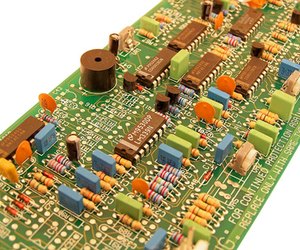
A capacitor is a circuit component that maintains voltage and discharges current over a matter of seconds when the voltage source is switched off. That's different from a resistor, which loses voltage virtually instantaneously compared to a capacitor. This feature of dissipating voltage slowly is called the "performance characteristic" of a capacitor. Bigger electronic capacitors are shown in the images but capacitors can be included inside a computer chip with other components. Never turn your computer on immediately after turning it off because you may put too much voltage over a capacitor and burn it out: then your computer won't function.
Testing a Capacitor
Step
Set up your breadboard so that the long end faces you. Inspect the breadboard and find the letters A through J across the top and numbers 1 through 63 along the side. Place the battery connector on the battery.
Step
Use an electrolytic capacitor with a 50-volt rating with a capacitance of 1 microfarad. Find the ground lead of the capacitor by looking for a "-" marking. Place that lead in position J20 on your breadboard. Place the other lead in position J25.
Measure the voltage decay of your capacitor. Place the black ground lead in position I20 to establish connectivity with the capacitor lead in J20. Note that continuity exists across each numbered row, including row 20. Turn your multimeter to VDC 20 (20 volts). Contact the black lead of the multimeter to the ground lead of the capacitor and the red lead to the other lead of the capacitor. Use alligator clips or hold them with your left hand.
Step
Apply voltage to the circuit by placing the red lead of the battery into I20. Read the voltage across the capacitor, which should be approximately 9 volts. Glance at your clock. Remove the read lead of the battery from I20 and check the discharge of the capacitor. Watch the voltage over the capacitor drop to 0 over the course of eight to nine seconds.
Step
Check continuity of the capacitor. Set the multimeter to the continuity check setting. Touch the black lead to the ground side of the capacitor and the red lead to the other side. If continuity exists (you'll hear a long beep), the capacitor is short-circuited and should be discarded.
Step
Set your multimeter to the highest ohms setting and apply it to the capacitor. Watch the meter approach 0 ohms and then start increasing. Keep the capacitor if it follows this general pattern.
Step
Use the voltage decay test and the continuity check as your determinative tests and use the ohms test as a rough check.
Step
Test a second electrolytic capacitor with a voltage rating of 63 volts and a capacitance of 6.8 microfarads. Construct a simple circuit with two resistors (each of 330 ohms resistance), the capacitor and a voltage source. Place one lead of resistor 1 in E63 and the other in E40. Place a lead of resistor 2 in D40 and the second lead in C25. Place the high lead of the capacitor in B25 and the ground (- or 0) in B23.
Put the battery ground lead (black) in A23. Put the red battery lead in C63. Set your multimeter to 20V and attach your red lead to the high capacitor lead (B25) and your black lead to the capacitor's ground (B23). Remove the voltage source and watch the voltage decrease. Expect voltage discharge times ranging from one minute and 12 seconds to one minute and 17 seconds.
Step
Note that the capacitance rating is within 20 percent, and there is often some variation.
This is a very practical and informative post—testing a motherboard with a multimeter is something many users find intimidating, but your explanation breaks it down in a way that's accessible without oversimplifying the process. It's also helpful that you emphasized safety and accuracy during testing, since working with hardware components requires a careful approach.
ReplyDeleteFor those who may not feel confident doing this kind of diagnostic themselves, it’s reassuring to know that there are experienced professionals who can help. I recently came across a helpful introduction to the team behind Same Day Geek, and it's clear how much value there is in having qualified techs who can handle both hardware and software challenges.
For computer repair businesses looking to grow their local client base, investing in local SEO services is also something to consider. It can really boost visibility for those offering reliable tech support in their area.
Additionally, as more people become dependent on their computers for work and personal use, including a disaster recovery and backup plan as part of a repair service package could make a big difference. Many users don’t think about data loss until it’s too late, so offering preventative solutions adds real value.
Thanks again for this clear and useful guide—it’s a great resource for anyone troubleshooting motherboard issues.